Conveying Parts

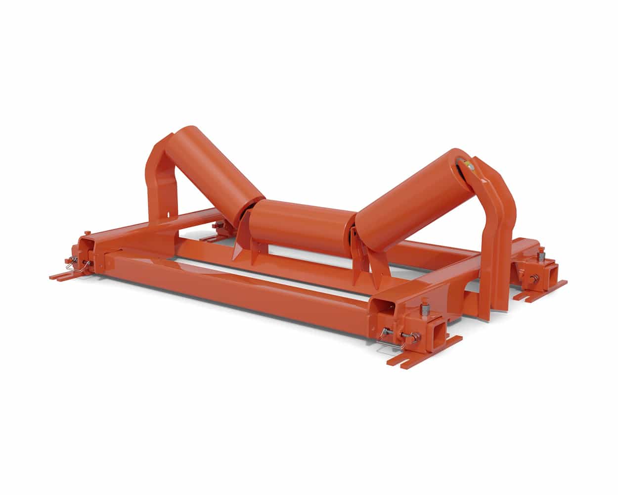
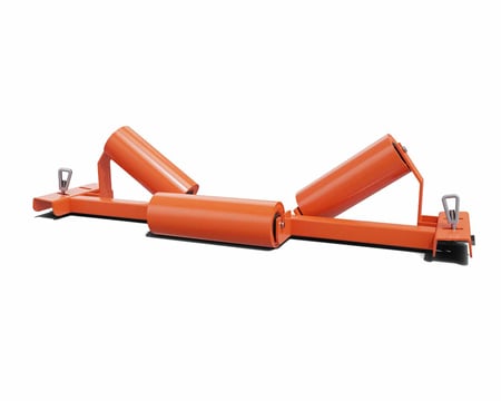
Self-Aligning Idlers

Hold the Line

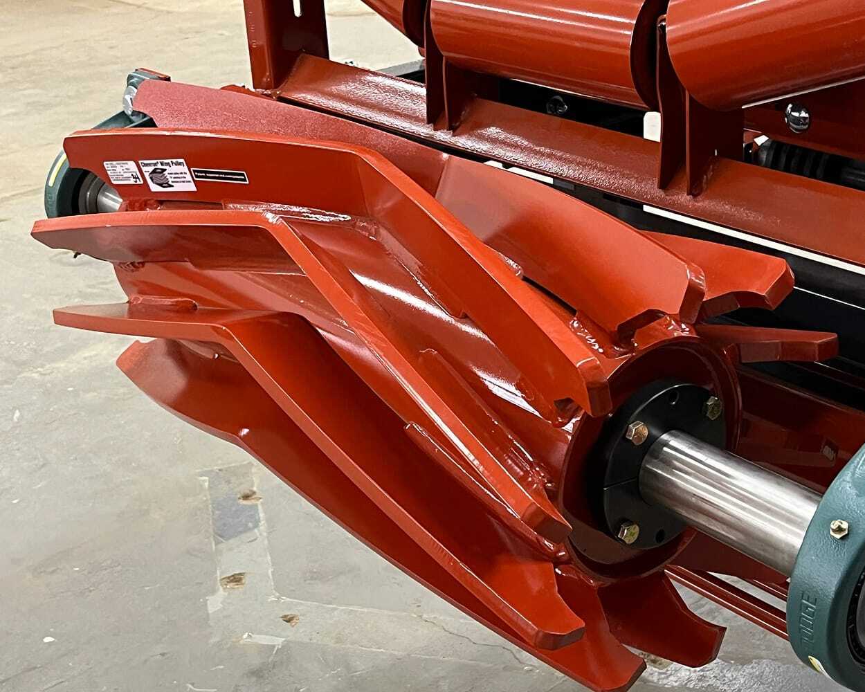
Belting is the most expensive component of a conveying system. Superior’s Self-Aligning Idlers ensure that your conveyor belts stay on track, minimizing the chance of severe belt damage.
Concave in shape, the idler’s side guide rollers restrain the belt from running up and over the conveyor. In order to lessen the wear on the belt, the side guide rollers are made with high-grade HDPE that reduces the friction between the idler and belt.

Applications
  • Label
  • Label
  • Label
  • Label
  • Label
belt-scale-1

Advantages

c5-35-ew-36-sales-spec-sheet-image-01-1

Troughing Idler

Short sentence describing the ideal applications for a troughing idler.

c5-35-ew-36-sales-spec-sheet-image-01-1

Troughing Idler

Short sentence describing the ideal applications for a troughing idler.

c5-35-ew-36-sales-spec-sheet-image-01-1

Troughing Idler

Short sentence describing the ideal applications for a troughing idler.

c5-35-ew-36-sales-spec-sheet-image-01-1

Troughing Idler

Short sentence describing the ideal applications for a troughing idler.

vertical-divider-dark-gray-2

The Next Generation Idlers

After decades of field testing and refinement, the next generation of idlers is here.
Superior just completed the biggest idler redesign of your lifetime. Millions have been invested in automated and modern manufacturing.
Reduce maintenance, reduce failure, and protect the belt. Get Superior-built steel idlers made to size for your specific application.

where to buy

Videos

Mojave Materials_Woodbine NJ_6-11-2025_018

Overhead view of 3055 Liberty Jaw crushing boulders

Mojave Materials_Woodbine NJ_6-11-2025_018

Overhead view of 3055 Liberty Jaw crushing boulders

Mojave Materials_Woodbine NJ_6-11-2025_018

Overhead view of 3055 Liberty Jaw crushing boulders

Images
Liberty Jaw General Specifications

Compare Liberty Jaw Crusher models, feed openings, capacities, and maximum feed sizes.

Standard Specifications
Model Weight Feed Opening CSS Capacity Speed Max Feed Size Power
kg lbs mm x mm in x in mm in mtph stph rpm mm in kW hp
2155B 16,500 36,400 530 x 1,400 21 x 55 40–130 1.6"–5.1" 90–400 100–440 280 427 16.8" 110 150
2636B 14,050 31,000 650 x 900 26 x 36 60–160 2.4"–6.3" 110–360 120–396 300 528 20.8" 75 100
3042B 15,700 34,600 750 x 1,070 30 x 42 70–200 2.75"–8" 150–500 165–550 280 610 24.0" 110 150
3343B 22,300 49,200 830 x 1,100 33 x 43 80–200 3.2"–8" 180–620 200–680 270 671 26.4" 110 150
3055B 26,950 59,000 760 x 1,400 30 x 55 70–200 2.75"–8" 240–780 265–855 260 610 24.0" 160 200
3455B 31,500 69,445 860 x 1,400 34 x 55 100–200 4"–8" 320–800 353–880 250 691 27.2" 160 200
3448B 28,000 62,000 860 x 1,220 34 x 48 70–200 2.75"–8" 170–560 185–615 250 691 27.2" 160 200
4051B 42,000 92,600 1,010 x 1,300 40 x 51 100–200 4"–8" 290–880 320–970 230 813 32.0" 160 200
4655B 52,500 115,800 1,160 x 1,400 46 x 55 150–250 6"–10" 400–900 440–990 230 935 36.8" 200 300
5165B 71,250 157,100 1,290 x 1,650 51 x 65 150–270 6"–10.5" 550–1,100 605–1,210 220 1,036 40.8" 250 350
6080B 135,000 297,000 1,525 x 2,030 60 x 80 200–300 8"–12" 700–1,450 770–1,595 200 1,219 48.0" 400 500
Gradation / Percent Passing
Size of Material Percent Passing for a Given Closed Side Setting - Average Feed Material (12-14 Work Index)
in mm 1.5" (38mm) 2" (50mm) 2.5" (63mm) 3" (76mm) 3.5" (88mm) 4" (101mm) 5" (127mm) 6" (152mm) 7" (177mm) 8" (203mm) 10" (254mm) 11" (279mm) 12" (304mm)
18 457                       100% 100%
16 406                     100% 98 94
14 355                     98 90 83
12 304                   100% 84 77 70
10 254               100% 100% 88 70 64 58
8 203           100% 94 80 70 56 51 47
7 177         94 82 70 61 49 45 41
6 152       100% 100% 82 70 60 53 42 38 35
5 127       100% 99 87 70 58 50 44 35 32 29
4 101   100% 100% 92 80 70 56 47 40 35 28 25 23
3 76 100% 95 83 70 60 53 42 35 30 27 21 19 18
2.5 63 95 85 70 59 50 44 35 29 25 22 18 16 15
2 50 85 70 57 48 40 35 28 24 20 18 14 13 12
1.5 38 69 52 42 35 30 26 21 18 15 14 11 10 9
1 25 44 34 28 23 20 17 14 12 10 9 7 7 6
0.75 19 32 25 21 18 15 13 11 9 8 7 5 5 5
0.5 12 22 18 15 12 10 9 7 6 5 5 4 4 3
0.25 6 12 10 8 6 5 5 4 3 3 2 2 2 1
Feed size is determined by measuring the longest one-way dimension of the material sample. Projected crusher capacities are based on a material having a work index of 12-14, with a bulk density of 100 lbs/ft3 (1.6 mt/m3). The feed grading must have less than 10% passing the crusher setting. The crusher drive assemblies are to be maintained in good working order with the ability to apply all available horsepower without drive belt slippage. Plant installation to ensure the crusher is able to operate continuously consuming the FLA rating of the motor(s) with the equipment able to accept and discharge material freely. For secondary cone crusher applications to be used in closed circuit applications consult Superior for capacity adjustments.

h2 / Impactful call-to-action headline here.

p.large / Small introductory paragraph that provides more context